Every now and then I still fall for it. Whenever I’m trying to accomplish something I’ve never done before, I start a Google search to find some nice video’s or blog posts that explain how I can accomplish this specific kind of task. That in itself is perfectly fine, however… one should not stop using its own brain!
This week I wanted to add an Inductive Proximity Sensor (LJ12A3-4-Z/BX) to my 3D printer as touching the printer bed while measuring the distance towards the printer bed has an actual effect on the measurement.. duh. Especially when you have a round aluminium printer bed that has supports at three “corners” only.
Side note (1): The main reason I own a 3D printer is that I’m into electronics – I like to built and program my own IoT hardware – and wanted to be able to print my own custom cases.
So let me refer you to some contents on the internet that explain how to install this proximity sensor:
They all tell you to work with a voltage divider as these sensors are powered by 6V to 36V, which means that their signal wire can be at that level to. Most 3D printer control boards however are Atmega based, which have max input of 5.5V. My MKS Base V1.5 printer board, is indeed based on an Atmega 2560 and suffers that same limitation.
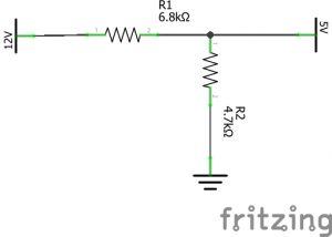
This all seemed very legit, so without thinking, I started to built a voltage divider, following their samples. I started out by combining 6.8kΩ and 4.7kΩ as this does stay within the standard range of “pull-up” values which is between 4.7kΩ and 10kΩ.
Tested my voltage divider with a 9 volts battery, and it all worked out fine. So let’s tear down my printer and add the proximity sensor. Installed the sensor together with the divider and… nothing! I then tested the voltage divider in combination with the sensor (don’t ask me why I didn’t test it with the sensor the first time) and noticed that the output, which should be around 5V, was around 2.5V only. OK, that might be an indication that the supplied current is not enough to maintain the “high” voltage when we are “pissing” away 2.5 mA towards Gnd. That is a bit weird as 2.5 mA is not that much, but let’s give it a try by using some higher value resistors. I don’t have the 15kΩ and 10kΩ mentioned in the video at hand so let’s take a 68kΩ and 47kΩ!

I was amazed as well, but indeed, this seemed to be the solution as the measured voltage now was 4.5V. Still to far off in my opinion, but it is high enough to pass as a logic high so let’s continue. Connect the sensor, configure the printer firmware and see what’s happening! Ehmm… nothing. Even though the sensor’s LED lights up when I approach it with something metal, the printer software still says NO.
Let’s take the digital multi meter at hand again and see what’s going on. We first measure the sensing pin on the printer board. I’m pretty sure I disabled the pull-up in the firmware so we should measure either a floating pin, or something close to GND.
Side note (2): In electronics we do not like floating pins. We either pull them softly, but fully, up towards Vdd or down to GND.
But wait! It reads a high 5V! That’s not good. Verified my firmware and the pull-up is indeed disabled, so did they add some hardware pull-ups?
Please tell me they didn’t. Because if they did add a standard hardware pull-up between 4.7kΩ and 10kΩ , I will indeed never be able to pull it down to LOW through the 68kΩ resistor in my voltage divider. OK, getting a bit tired of it but, never give up and search for the schematics on the printer board then.
You can find some sort of design of the board on GitHub, but that is not detailed enough. Luckily I found someone with the same issue that I had and he had a solution! Hurrah, all I needed to do was to remove some resisters from the printer board and then it will all work. So I prepared my soldering iron to attack my printer board and then……
NOOOOOH, of course not. It was just then when I finally decided to use my own brains. I should be able to solve this myself! Serious? I almost got medieval on the ass of my printer board with a soldering iron.
So let’s use our brain and look at the schematics of these type of sensors.
The sensor type I’ve got is NPN NO which means that you measure the BLACK line and:
- when it is not sensing anything inductive nearby, it should be open and thus floating
- when it is sensing anything inductive nearby, it will be connected to GND
Hmmm… floating. Remember when I said we don’t like floating pins in electronics? We would like to have either all or nothing. So in this case, the following will most probably be true:
- when it is not sensing anything inductive nearby, it will be pulled up to Vdd
- when it is sensing anything inductive nearby, it will be connected to GND
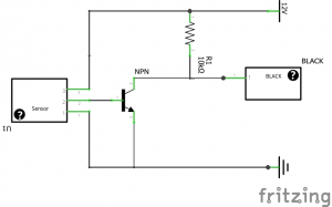
So let’s draw a logical design on how an NPN transistor with a pull-up would look like.
We should be able to measure that with a digital multi meter. Just measure the resistance between BLACK and BROWN. I did and guess what? I indeed measured an almost perfect standard pull-up value of 10kΩ.
But wait a second… that’s why our voltage divider gave such weird values! What we thought was this:
Actually was this:
And that’s why it all didn’t work. Once we started to create a voltage divider with insane values it started to work as the 10kΩ did not have that high of an impact any more.
We can now also answer the question of how we actually should connect our NPN sensor to our printer board. We do need a voltage divider, but one of the resistor values is already given. We can use the following formula to calculate the required value of the second resistor R2:

Or navigate to http://www.ohmslawcalculator.com/voltage-divider-calculator if we are lazy.
The output should be 7142.86Ω.
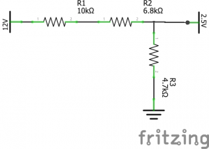
To be on the safe side we pick a standard value which is less so we end up with 6.8kΩ. Our final solution just looks like this:
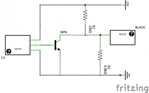
Indeed, all we need to do is add a single 6.8kΩ resistor between BLACK and BLUE and all should work fine.
Once the single resistor was added, I verified all voltages with my digital multi meter and it all worked perfectly fine.
Don’t forget that you do need to change your firmware because we still need to invert our end stop. It is HIGH when not triggered and LOW when triggered.
const bool Z_MIN_ENDSTOP_INVERTING = true;
So after all I got it working in the easiest, cheapest and most logical way one can, simply by using my own brain.
The moral of this story is to never stop thinking yourself and to not blindly trust all stories on the internet. Use your brains!
That being said! Don’t just do as this posts says! First you have to verify which type of sensor you’ve got. If you have a NPN type of sensor, you should be able to measure the 10kΩ pull-up resistor between BROWN and BLACK. If you have a PNP type of sensor, you will most probably(I don’t own one) be able to measure the 10kΩ pull-down resistor between the BLACK and BLUE. In case you’ve got a PNP type of sensor, the very first voltage divider should indeed be used.
One thing is sure. IF you do connect your sensor to 12V (which you should as that is within the specs!) you should not go without any voltage regulation, even though many people suggest you should. It doesn’t matter which type of sensor, you should not connect them as is to your signal wire if the sensor is connected to 12V.
***UPDATE***
Boris had a perfect comment on using a diode instead. And, believe it or not but, using a 1N4148 diode was my first solution. So I did test using a diode and that also works perfectly fine, simply because the direction in which the 12V current would like to flow when the sensor is open will be blocked by the diode. The internal (or hardware) pull-up still pulls the Atmega’s sensor pin to HIGH however.
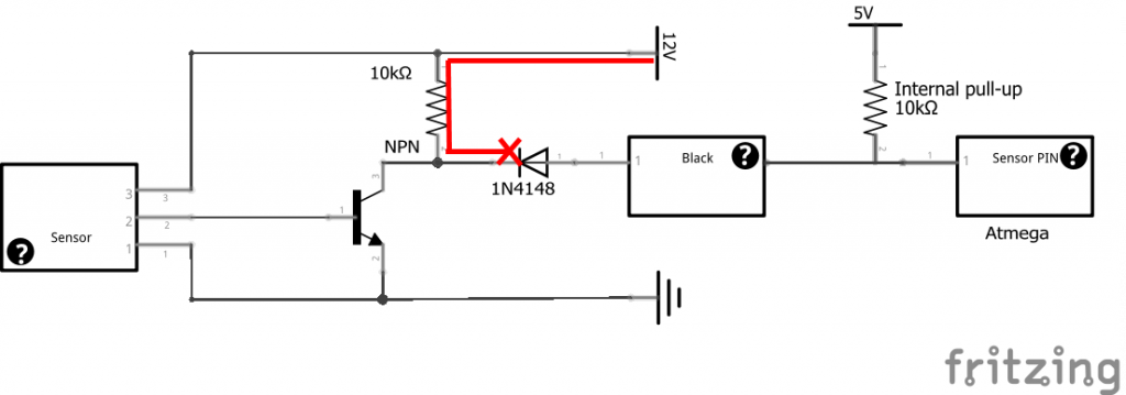
But as soon as the sensor is closed, the diode would allow the 5V current to flow in the opposite direction towards ground, which pulls the Atmega’s sensor pin to LOW.
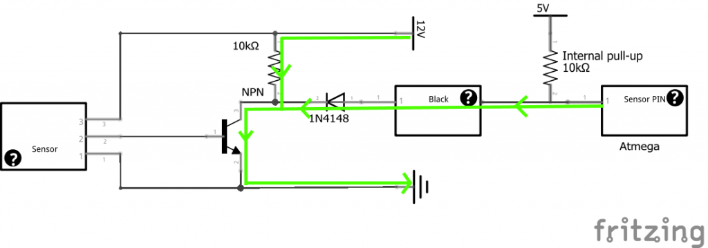
So both the proper voltage divider and a diode can do the job. Which one you prefer… well, the diode might actually be safer to use (they often call it a protection diode with a reason ;-)) if installed correctly, but it also depends on what you have at hand and even what you prefer I guess. The reason I preferred to explain the voltage divider in the first place, is that one cannot wire the resistor in the wrong direction. If you do that on the diode, you will permanently damage your printer board.
***UPDATE 2
While I was watching referrals to this blog post I noticed some Swedish(?) web site. When I looked at that blog post (after translation) it showed an ever better way of connecting the sensor to the printer board by using an opto coupler. I know a lot of people don’t have one of these lying around, but if you do… you can’t be any safer. Check it out here.
***UPDATE 3
Some people were still struggling with the diode implementation, so I created a picture walk-through on how the diode method works. The walk-through can be downloaded over here.