Every now and then I still fall for it. Whenever I’m trying to accomplish something I’ve never done before, I start a Google search to find some nice video’s or blog posts that explain how I can accomplish this specific kind of task. That in itself is perfectly fine, however… one should not stop using its own brain!
This week I wanted to add an Inductive Proximity Sensor (LJ12A3-4-Z/BX) to my 3D printer as touching the printer bed while measuring the distance towards the printer bed has an actual effect on the measurement.. duh. Especially when you have a round aluminium printer bed that has supports at three “corners” only.
Side note (1): The main reason I own a 3D printer is that I’m into electronics – I like to built and program my own IoT hardware – and wanted to be able to print my own custom cases.
So let me refer you to some contents on the internet that explain how to install this proximity sensor:
They all tell you to work with a voltage divider as these sensors are powered by 6V to 36V, which means that their signal wire can be at that level to. Most 3D printer control boards however are Atmega based, which have max input of 5.5V. My MKS Base V1.5 printer board, is indeed based on an Atmega 2560 and suffers that same limitation.
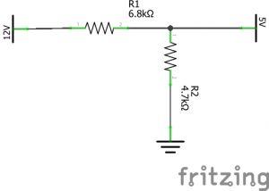
This all seemed very legit, so without thinking, I started to built a voltage divider, following their samples. I started out by combining 6.8kΩ and 4.7kΩ as this does stay within the standard range of “pull-up” values which is between 4.7kΩ and 10kΩ.
Tested my voltage divider with a 9 volts battery, and it all worked out fine. So let’s tear down my printer and add the proximity sensor. Installed the sensor together with the divider and… nothing! I then tested the voltage divider in combination with the sensor (don’t ask me why I didn’t test it with the sensor the first time) and noticed that the output, which should be around 5V, was around 2.5V only. OK, that might be an indication that the supplied current is not enough to maintain the “high” voltage when we are “pissing” away 2.5 mA towards Gnd. That is a bit weird as 2.5 mA is not that much, but let’s give it a try by using some higher value resistors. I don’t have the 15kΩ and 10kΩ mentioned in the video at hand so let’s take a 68kΩ and 47kΩ!

I was amazed as well, but indeed, this seemed to be the solution as the measured voltage now was 4.5V. Still to far off in my opinion, but it is high enough to pass as a logic high so let’s continue. Connect the sensor, configure the printer firmware and see what’s happening! Ehmm… nothing. Even though the sensor’s LED lights up when I approach it with something metal, the printer software still says NO.
Let’s take the digital multi meter at hand again and see what’s going on. We first measure the sensing pin on the printer board. I’m pretty sure I disabled the pull-up in the firmware so we should measure either a floating pin, or something close to GND.
Side note (2): In electronics we do not like floating pins. We either pull them softly, but fully, up towards Vdd or down to GND.
But wait! It reads a high 5V! That’s not good. Verified my firmware and the pull-up is indeed disabled, so did they add some hardware pull-ups?
Please tell me they didn’t. Because if they did add a standard hardware pull-up between 4.7kΩ and 10kΩ , I will indeed never be able to pull it down to LOW through the 68kΩ resistor in my voltage divider. OK, getting a bit tired of it but, never give up and search for the schematics on the printer board then.
You can find some sort of design of the board on GitHub, but that is not detailed enough. Luckily I found someone with the same issue that I had and he had a solution! Hurrah, all I needed to do was to remove some resisters from the printer board and then it will all work. So I prepared my soldering iron to attack my printer board and then……
NOOOOOH, of course not. It was just then when I finally decided to use my own brains. I should be able to solve this myself! Serious? I almost got medieval on the ass of my printer board with a soldering iron.
So let’s use our brain and look at the schematics of these type of sensors.
The sensor type I’ve got is NPN NO which means that you measure the BLACK line and:
- when it is not sensing anything inductive nearby, it should be open and thus floating
- when it is sensing anything inductive nearby, it will be connected to GND
Hmmm… floating. Remember when I said we don’t like floating pins in electronics? We would like to have either all or nothing. So in this case, the following will most probably be true:
- when it is not sensing anything inductive nearby, it will be pulled up to Vdd
- when it is sensing anything inductive nearby, it will be connected to GND
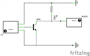
So let’s draw a logical design on how an NPN transistor with a pull-up would look like.
We should be able to measure that with a digital multi meter. Just measure the resistance between BLACK and BROWN. I did and guess what? I indeed measured an almost perfect standard pull-up value of 10kΩ.
But wait a second… that’s why our voltage divider gave such weird values! What we thought was this:
Actually was this:
And that’s why it all didn’t work. Once we started to create a voltage divider with insane values it started to work as the 10kΩ did not have that high of an impact any more.
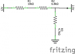
We can now also answer the question of how we actually should connect our NPN sensor to our printer board. We do need a voltage divider, but one of the resistor values is already given. We can use the following formula to calculate the required value of the second resistor R2:

Or navigate to http://www.ohmslawcalculator.com/voltage-divider-calculator if we are lazy.
The output should be 7142.86Ω.
To be on the safe side we pick a standard value which is less so we end up with 6.8kΩ. Our final solution just looks like this:
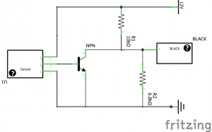
Indeed, all we need to do is add a single 6.8kΩ resistor between BLACK and BLUE and all should work fine.
Once the single resistor was added, I verified all voltages with my digital multi meter and it all worked perfectly fine.
Don’t forget that you do need to change your firmware because we still need to invert our end stop. It is HIGH when not triggered and LOW when triggered.
const bool Z_MIN_ENDSTOP_INVERTING = true;
So after all I got it working in the easiest, cheapest and most logical way one can, simply by using my own brain.
The moral of this story is to never stop thinking yourself and to not blindly trust all stories on the internet. Use your brains!
That being said! Don’t just do as this posts says! First you have to verify which type of sensor you’ve got. If you have a NPN type of sensor, you should be able to measure the 10kΩ pull-up resistor between BROWN and BLACK. If you have a PNP type of sensor, you will most probably(I don’t own one) be able to measure the 10kΩ pull-down resistor between the BLACK and BLUE. In case you’ve got a PNP type of sensor, the very first voltage divider should indeed be used.
One thing is sure. IF you do connect your sensor to 12V (which you should as that is within the specs!) you should not go without any voltage regulation, even though many people suggest you should. It doesn’t matter which type of sensor, you should not connect them as is to your signal wire if the sensor is connected to 12V.
***UPDATE***
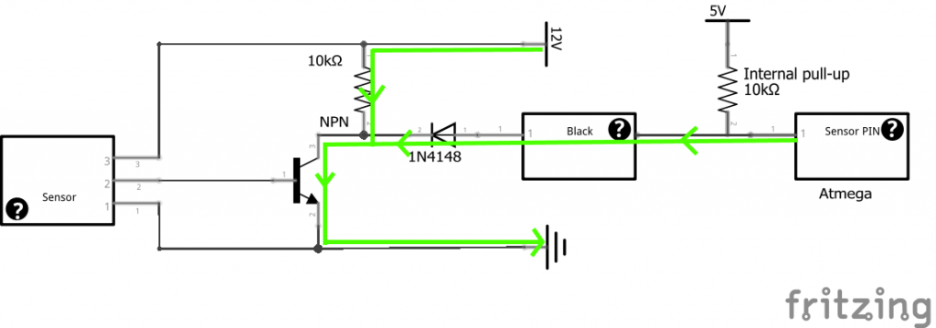
Boris had a perfect comment on using a diode instead. And, believe it or not but, using a 1N4148 diode was my first solution. So I did test using a diode and that also works perfectly fine, simply because the direction in which the 12V current would like to flow when the sensor is open will be blocked by the diode. The internal (or hardware) pull-up still pulls the Atmega’s sensor pin to HIGH however.
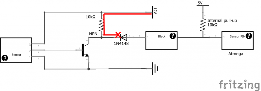
But as soon as the sensor is closed, the diode would allow the 5V current to flow in the opposite direction towards ground, which pulls the Atmega’s sensor pin to LOW.
So both the proper voltage divider and a diode can do the job. Which one you prefer… well, the diode might actually be safer to use (they often call it a protection diode with a reason ;-)) if installed correctly, but it also depends on what you have at hand and even what you prefer I guess. The reason I preferred to explain the voltage divider in the first place, is that one cannot wire the resistor in the wrong direction. If you do that on the diode, you will permanently damage your printer board.
***UPDATE 2
While I was watching referrals to this blog post I noticed some Swedish(?) web site. When I looked at that blog post (after translation) it showed an ever better way of connecting the sensor to the printer board by using an opto coupler. I know a lot of people don’t have one of these lying around, but if you do… you can’t be any safer. Check it out here.
***UPDATE 3
Some people were still struggling with the diode implementation, so I created a picture walk-through on how the diode method works. The walk-through can be downloaded over here.
Good job, smart done and clear explained.
May I ask you something. I’m fighting with MKS Gen-2z v1.1 board on 3D printer. It has a standard hardware pull-up resistor. Now trying to use NPN NO capacitive sensor (LJC18A3-H-Z/BX) for autobedleveling. Already played with voltage divider from Tom’s guide etc. Got floating values, as you did. After reading your article I measured resistance between brown and black and it is infinite. The resistance between black and blue is 1.15 kOhm. Made double check: it is NPN NO sensor. Any ideas?
Update: I used 7.3 kOhm resistor (just did not have other closer to needed value) as you described. In firmware I have disabled pull-up resistor. Now sensor state is reproducibly shown as Low when not triggered and High when triggered (checked using M119 and G31 commands). By the way it shows 5.37 v and 120 mcA when not triggered and 3 mV and 1 mA current when triggered.
I thank you SO MUCH for your investigation! If you don’t mind I will post links to your blog at the places where other lucky owners of MKS Gen-2z boards with built-in pull-up resistors will probably look for the solution: groups of Sunhokey printer owner at thingiverse.com, facebook, 3dtoday.ru.
Thanks again!
Nice to hear it worked out for you. Please feel free to share this information in any form you like. You can even copy the contents to your own blog if you like. As long as the information is shared and you don’t charge people money for it, I’m fine with it.
Here are recommendations about using diode. I don’t quite understand how it works. Solution with resistor looks safer for me, because diode failure is much more probable than resistor failure 🙂 https://www.facebook.com/groups/sunhokeyprusai3owners/1407992025924842/
Quote from there:
James Brown The NPN sensor drives low when activated, if you have a voltage divider, it may not work properly. The voltage divider will itself form a divider with the on-board pull-up, preventing the signal going fully low; depending on resistor values it might or might not work. A better solution is to use a reverse biased diode, when the sensor drives high, the diode blocks the signal (too high a voltage for the board), when the sensor drives low, the board pin is pulled down to ~0.7V (one forward diode drop).
Thanks for your reply. The diode was my first solution but I eventually went with explaining the divider as this allows me to actively pull-up instead of relying on the hardware or software pull-up. Besides that, the resistor cannot be wired in the wrong direction as can be done with the diode, which would damage the printer board.
But, to prevent confusion on what to use I decided to update the post to reflect the diode option. It makes it more complex as a whole, but at least, it is now complete.
For those people that are wondering if you could combine the two: “Yes you can!”. But the resistor would be completely redundant until the diode somehow shorts out, or is installed in the wrong direction. In the latter case you would not damage your printer board, but the head would crash into the bed as its hardware or software pull-up current will be blocked from flowing away to ground by the diode. But I sure hope you at least test the “switch” before you start a bed level.
Actually diode solution is technically way better and only has one downside it will require pull-up on the board side, but you may just enable internal one on microcotroller. Problem with resistor dividers – if you switch/update your board and add/change internal pullup it will brake your divison. Also “divison” gives you “analog” signal, so unless you are quite precise you maybe easily affected by noises etc as your divided signal is not digital so it can be close to 0/1 switch level. Also divison depends on pullup value on sensor and voltage, so you replace sensor or change voltage you can have bad effects. Worse thing you may have fluctuations so it will be difficult to detect why you do not have proper sensing sometimes. Diode on another side will provide digital signal, so it would not care what internal pullup you have (unless you have very low, but that is nonsense). It does not care what voltage you submit to sensor and what is internal pullup for that sensor is. And “diode” failure is very unlikely (unless you chosen very low voltage one). So resistor divider is clumsy solution in my opinion.
On top of that – diode solution will work with open collector NPN (no pullup) as well as NPN with pullup. It also will work just fine with PNP with pull down resistor (if board/microprocessor is not too low). It will only not work with open collector PNP. I think they should just add diode into Z probe (or put additional input with it) as it is almost perfect solution.
2 Boris: just add up. You think that resistor solution is “safer”. Let me point you to a small detail. You said after your divison it currently shows 5.37V. Congratulations, you are very close to burn your input! If you have arduino mega with Atmega2560 (which is quite probably) it has rating for max input voltage as Vcc + 0.5. So if your power supply is precise and provides 5V exactly you are 0.37V over and 0.13V to the maximum. I would be scared already. Note if your arduino power supply for whatever reason would drop the voltage a little bit (0.13V is not that match), you will most probably burn your input. Or for example internal pullup of that sensor would decrease resistance (which could easily happen due to temperature change and heater element nearby). Do you already fill safe with this solution vs danger of switching diode inputs?
For thick glass bed (>3mm), use Omron E2BM18KN16WPC12M 16mm NPN inductive sensor. Also, it has better circuitry that doesn’t require resistor or diode.
http://www.mouser.com/Search/ProductDetail.aspx?R=E2B-M18KN16-WP-C1_2Mvirtualkey65350000virtualkey653-E2BM18KN16WPC12M
It indeed looks like the Omron E2BM18KN16WPC12M 16mm NPN inductive sensor does not have an internal pull-up and thus can be used safely without any voltage regulating at all.
Did you test this with a digital multi meter yourself?
Yes, I tested and the output is 5v floated/connected\ when powered by 12V.
Perfect. Thanks for letting us know.
I tried the optocoupler 4N25 as described in the Swedish blog post – it didn’t work. I’ve seen other articles where people are applying 12V and a 1KOhm resistor to the cathode, and the signal pin to the anode … anyone have a capacitive NPN NO sensor working with a 4N25 or optocoupler ?
only on a MKS BASE v1.4
I had the same problem and i fix it like you.
Thanks!!!
I tried the ***UPDATE 2 from the Swedish site. Unfortunately 1K ohm can only drop voltage to 2.5V and controller still accepts is as HIGH. After replacing the R with a 2.2 ohm. I got 2 Volts and it was enough for the controller for returning LOW. I tried it with 12mm NPN and 18mm NPN (both inductive) and 18mm Capacitive all worked but best was capacitive one.
have you been able to get lower than 2v FLOAT?? i aswell Dropped down to 2V with a 2.2ohm Resistor, but id actually like an official LOGIC LOW of 1.0-1.5volts
forgot to mention im using a MKS GEN v1.4.
My solution was just to change the signal pin to a not used one on my mks gen 1.4. I took pin 44(aux 2)and in the ramps pin file changed the z min endstop pin to 44. Reflashed marlin and it worked.
Going through the datasheets I did not found this pin to have a higher voltage rating. Can you point us to any reference that states that 12 Volt on this pin is supported?
I did not feed it with 12 V. I used the 5 V and the gnd directly from the endstop connection. So the braun wire of the LJ12A3-4-Z/BX Inductive Proximity Sensor Switch NPN no connected to 5V, the blue wire connected to gnd and the signalbwire to pin 44.
The black wire is the one that is connected to pin 44.
I also have a prusa i3 with a rumba board where I just connected the 3 wires off the lj12a3-4-z/bx(npn no) directly on de z min endstop connection. Only the endstopconnection of the rumba is not fitted with pullup resistors that one works straight away.
Thank you very much, it helps!
I use a schottky barrier diode instead of 1N4148 for it has a faster reaction.
uncomment PROBE_DOUBLE_TOUCH in marlin, it now has a tolerance of less than 0.05mm
i have lj12a3-4-z/by PNP/NO type
and A8 printer, i still cant good wiring to tell me what to do ….
As it is a PNP NO sensor, you should measure either floating or GND when not sensing anything nearby or input V+ when sensing anything nearby on the BLACK wire.
Input V+ should be between 6V-30V. Based on the input voltage you use (12V?) and any pull-down resistors (internal or external) attached to the BLACK wire to prevent it from floating, you should calculate the required voltage divider.
I would recommend you to start by measuring the resistance between BLACK and BLUE wire. This will give you the value of an internal pull-down resistor if any.
when using a ramps, on what pins would you install your cables?
Unfortunately I do not have the datasheets of your printer board (ramps version?) or your sensor, so I cannot help you out here.
I just had the same issue and i had come to the same exact conclusion, funny how i also came across the guy that gave advice to remove the onboard pullup resistor lol anyways thanks
Hello, can you please redraw a final version with a diod for dummies (people who do not have experience to read schematics)? Like blue wire does here, brown there etc.
Also i saw alot of people hook up old end stop sensor as backup measure, to prevent events when proximity probe failed. That switch have 3 nodes, i cant understand how to wire the electronic trigger chain (com, nc and something i cant recall)
Thank you very much! This was really helpful and solved my problem!
However, for safety puroposes, I first tried the higher resistors first (47K on signal and 32K divider) which did’t work despite outputting the correct voltage.
Finally I tried the simplest solution with the 6.8K resistor divider (I actually used 4.7K + 2.2K since I didnt have the 6.8K) and it worked out just fine.
Thank you very much for your tutorial, it was very helpful.
However, I encountered a problem when installing the sensor with the diode. Measuring, I see the almost 5V when sensing and almost 0V when not. But, when I connect it on my Megatronics v2, sending the M119 command (Marlin FW) I always get an open Z sensor. I already checked if I might have busted my electronics, but it is not the case, as the switch works fine, triggering when pressed.
I really want to have autoleveling on my printer and I don’t know if I might have busted the sensor, but I suspect not.
Could you be so kind as to give me a nudge in the right direction?
Hi, I think I might have a working theory.
On my board I have a RepRap full graphics LCD with the navigation wheel, and that just drew too much current to be handled by the on board 12-5V regulator, so I separated the 5 and 12V circuits by removing a jumper and power the 5V side through the USB, connected to the power supply.
Might this be separating the 5V and 12V grounds, making impossible the passing of the current?
Thanks in advance.
Unfortunately I don’t know as I don’t know the schematics of the board. Maybe someone else can help you out?
Hello, my friend! Here is Boris again. Glad to talk to you after a year. LJC18A3-H-Z/BX, than LJC12A3-5-Z/BX, voltage divider 6.8 kOhm. Suddenly I encountered a strange problem. By the hotend heater turned off the sensor works fine. But if I turn the hotend heater on the distance at which the sensor detects objects increases by 2-4 mm. And it also is not a distance but a range: it turns on at say 2 mm and off at 4 mm. I have turned off all power consumers and disconnected the wires of hotend heater and made sure the voltage between brown and blue is 12.03V. But the strange effect is present. And there is no voltage drop (still 12.03V) when I turn physically absent heater on. I thought may be something was wrong with Ymax pin I used for signal. Changed the pin to other digital pin -> same story. And obviously I changed the sensor to a brand new one -> same story. Any ideas how turning on an absent hotend heater may influence the sensor without changing its voltage?
Found your page and read it, nice description. I do not quite understand one thing, if signal output is NPN open collector pulling to ground why do you pull it to 12V creating problem you are trying to solve with divider or diode? Why just not to pull to 5V or 3.3V depends what you use there?
Funny, I have removed 6.8 kOhm resistor and used the diode. If hotend heater is physically disconnected there is no problem. But if the heater is connected problem reappears. The voltage drop on brown-blue pair is 0.2V (from 12.0 to 11.8). But this is more than enough for sensor to work. Usually it is vice versa: higher is the voltage on sensor longer is the distance it detects objects. But here we turn heater on, voltage on sensor drops by 0.2V and sensor gets activated by the table remaining on the same distance as before.
O, God, I’ve found the problem. I have installed 220V heater under the heatbed and have connected the aluminum table to the ground. PSU was also connected to the ground and it sends some “noise” there. If PSU is disconnected from ground measurements get precise again. Now I need two separate “grounds”: one for table one for PSU. Good, that the bug is found. Thank you for being there and giving “spiritual” support!
You are a champ! Thank you for reporting back here as this might help out others!
I tried the “Swedish” method and it didn’t work. What I’m seeing is zero volts when not sensing, and a VERY slow increase in voltage from zero when sensing is triggered. I then noticed that the sensor he’s recommending is a PNP whereas this guide is (mostly) working off the assumption it is an NPN. I have to admit, I don’t understand the difference.
I also saw one commentor saying he substituted the 1Kohm for a 2.2Ohm… that’s a HUGE difference. So is the 1Kohm a typo or the 2.2 Ohm?
I’d like to get this working and hope someone can help.
i tried this aswell with 1k ohm and 2.2 ohm with OPTO. i cant get it to drop below 2.30volts
Hello. I have the same exact probe (LJ12A3-4-BX) connected to a RAMPS and 12v . I tried a voltage divider with values of 4.3 ohms and 1.8 ohms. it did not work. I get a voltage reading of a few millivolts at most. like 2.2 mv open and 1.3 mv closed.
The crazy thing is, when I first got the sensor, I was eager to try it out. Reading on the net that i can connect it directly to the board, i did, brown to 12v and the other two pins to gnd and sig.
That was the only time the thing actually worked flawlessly.
Now it reads triggered all the time, regardless if i activated the PULLLUPS option or not.
Sorry to be the one telling you but, you’ve probably blown your signal pin by putting 12V on it, which is more than double than what it is rated for.
Yeah i thought that too. But i connected an active mechanical endstop (three wires) and it works fine.
I tested again now. My sensor pulls the signal wire high when not engaged and pulls it low when engaged (metal detected).
Like u said, resistor divider using values of 4.1 and 1.8 ohms does not work. Output voltage is the same as input.
What resistance do you measure between black and brown?
Resistance between brown and black 3.35 Mohm
That might be caused by weak pull-up. Have you tried a 2.2 Mohm resistor between the Black and Blue wire?
by the way, the link to the swedish post is now in english on another page. the current link in your page is dead. here is the new link
http://pnordin.se/auto%20bed%20leveling%20en.html
Thanks, updated the link
I don’t have such a large value resistor at hand now. If i really need it I’ll buy it.
Mind you that I don’t know for sure if that’s the solution, but if you can get your hands on it easily you should.
Resistors on their way now. Will try tomorrow your suggestion.
Your want me to try the 2 mohm resistor is series with a voltage divider? Or just use the resistor and report back voltage?
Just place the resistor between the black and blue wire only and then measure the remaining voltages at the black wire on both states (open & close) when brown is connected directly to 12V and blue is connected directly to gnd.
sorry i couldn’t get the 2mohms resistors. but i got the diode and optocoupler.
going to try the diode first, as this is the easiest and closest to my situation as per this youtube video from Tech2C
https://youtu.be/wih4fNkKUCc?t=601
I used diode 1n4148 in series on the signal wire to test the theory that it should block the 12v high signal when probe not engaged. To better understand, i tested all scenarios with and without the diode, these are the results.
with no diode
positive multimeter terminal on signal and negative used to probe the positive and negative terminals on the board. i observed the following results:
==probe not engaged:
with no diode:
signal to negative: 11.36v
signal to positive: -0.625v
with diode:
signal to negative: 14.65v
signal to positive: -6.7v
==probe engaged:
with no diode:
signal to negative: 4.6mv
signal to positive: -12v
with diode:
signal to negative: -6.7v
signal to positive: -15v
I’m not good at understanding electronic circuits, but I’m pretty sure those numbers make no sense to me.
Hi, can you make a picture on how you connected the diode? Doesn’t make sense to me either.
Hello, sorry i since dismantled the test circuit, as it wasn’t working. The diode was with the black circle facing the sig wire. Anyway i tried it both ways just to be sure.
What i did find out, by chance, when trying the optocoupler circuit, is that a simple 1 ohm resistor between sig and ground have me a 4.6v high when not engaged and reverse when engaged. So that did the trick i believe. The optocoupler have me an output of a few millivolts, so i didn’t bother using this approach
Ah, that explains a lot. The diode should be between the board and the signal wire, with the marked end facing the signal wire.
Yeah that’s what i did. Diode marked end towards the sig wire
The best solution seems to be the PCB mentioned by Thelvaen.
Just to mention i finally finished the circuit and it works fine now. Here’s the final connection diagram i made. Sorry it’s messy.
https://drive.google.com/file/d/18m8A5JEZyS-f8yMtLamtvVqShTRxGy8X/view?usp=drivesdk
No worries. In your solution you could drop the two resistors and one diode. The remaining diode can be turned 180 degrees and you’ll have my 1N4148 diode solution which is mentioned in the UPDATE. You will now definitely get a 0V on the LOW. To ensure a HIGH on not sensing you can enable the internal pull-ups from the software OR ad a 10kOhm resistor between 5V on the motherboard somewhere and the signal pin directly.
I tried everything else, including the solutions you mentioned.
problems is, my sensor is different, like i mentioned before. when sensor is not engaged, it already gives a high 12v, without any pull-ups. and in engaged mode, it gives a low with 12v. thats why i added the two diodes. the resistors are there to drop the voltage to 3v (or 2.8 after diode v-drop).
unfortuantely, nothing from this circuit can be removed. believe me, i’ve tried every other combination possible.
i added the diagram for anyone else having the same sensor i’m having and behaving the same.
Please do read the document I created for you over here. Your sensor should work exactly the same.
And what about the case when I have 5V sensor connected directly to z-stop socket (all 3 pins)?
I measured it and when sensing nothing, there is 0,6V between black and blue. When sensing some item, there is 2,3V between black and blue. So no high state… Do You have any suggestions?
Is it possible to use that type of sensor?
I ment between black and brown
You can use a weak (10kOhm) pull-up resistor for the high state.
Thanks for your post, it reminded me that I should not forget everything I’ve learned at school about electronics (and that was quite extensive as I’ve studied in that field), and think by myself (even if the IT guy I’ve became tends to think that it’s useless to invent the wheel again).
By the way, while searching for solutions too, I have never been really happy with the floating component solution, and being quite reluctant at engineering a board for this, I’ve came across that product : https://www.reprap-france.com/produit/1234568387-carte-dinterfacage-de-capteur-inductifcapacitif that is doing just what we’re wanting to do here.
Indeed, never reinvent the wheel again, but make sure you understand how the wheel you’re using works. The solution you’ve found is the best solution. Nice board, not too expensive. Thank you for bringing it under our attention.
okay i got a LJC18A3-8-Z/BX(CAP SENSOR) to work with a 1k ohm, and OPTO on a MKS BASE V1.4(same as swedish Site), but now im trying a LJ18A3-8-Z/BX(INDUCTIVE) sensor with opto, and 1k ohm resistor and i cant get to drop below 2.30volts on a MKS GEN V1.4. PLZ PLZ anyhelp!! Thank You.
ABOUT freaKING TIME!! I just got it to work with a 2.2ohm+ OPTO, and LJ18A3-8-Z/BX INDUCTIVE Probe on MKS GEN V1.4. HIGH is 4.99v, and LOW is 2.0volts. Had to disable ENDSTOP PULLUPS in FIRMARE. Now im wondering if ill be able to make the LOWa bit lower? like to 1-1.5volts?
Dave, do you have a schematic on how you connected your sensor?
I used the Swedish diagram, and switched the resistor
You know you could use a zener diode to act as a voltage regulator.
Zener diode combined with a resistor that is.
True. And if you really want to get picky, you could put a smoothing cap on it too.
https://www.youtube.com/watch?v=aIAGrH6txq0
I haven’t watched the video, but I hope the smoothing cap is not in the signal wire as it effects the signal speed.
Yeah – I was kind of brain dead when I made that comment. I was thinking of when using it on just a power path, not a signal path.
😀
Aren’t you making things waaaayyy to complex for yourself? The sensor has an open collector output. All it needs is a pull-up resistor. And that does not have to pull up to 12 Volts! It will work fine if you pull it up to 5 volts. And the pull-up to 5 Volts… Is already in your ATMega.
So you can simply connect the black wire to the input. No additional parts needed!
It does NOT have an open collector, it has an internal pull-up to 12V! That’s the whole issue.
Duuuude, you just saved my life sir!
Thank you for this. It was very helpful.
I just completed my conversion using the diode method. Simple, straightforward, cheap (for the diode), no math needed, and as long as you put the diode in the right direction, protects against overvoltage. What’s not to like?
how about for a 24v system like the ender 3/pro? how would one set that circuit up. i’ve seen some diagrams for using an optocoupler board ,but those take like 5-6 weeks to arrive from china.
could i just use a relay board like this instead?
https://www.amazon.com/gp/product/B01L1OI1HC/ref=ppx_yo_dt_b_asin_title_o06_s00?ie=UTF8&psc=1
jason, just use diode with more than 24V reverse voltage with NPN sensor, and it would not care if you have 12V or 24V on your sensor.
Sorry for my late reply, but it looks like a 12V rated only optocoupler board. You probably can make it work if you change the resistor though…
Creality boards are “known” to be damaged when using 24V, so I would not try using an Ender 3 with 24V, without changing the board to something a bit more robust.
Besides you’ll have to change the heat cartridge and heat bed too (depending on your version, you might not be able to rewire it to get it working with 24V).
Im using a LJ18A3–8-Z/AY and in wont trigger the board.
The untriggered voltage is about 4,8V and triggered 3V.
I already tried a diode. And im currently using 2 resistors.
My board is a MKS GEN L
i need help setting my LJ18A3–8-Z/AY PNP sensor up. I already tried with a diode but it did not work. The triggered voltage was always over 3V. And untriggered at 4,8-5,2V.
Marco, PNP is more complicated. First of all you need to disable internal pull-up and may check if that sensor does have embedded pull down resistor. If it does not or your board has pull up you may need to add another pull down before diode, or even better to add a NPN transistor. Which would be probably too complicated, so you may better get a NPN sensor instead.
Actually you cannot disable internal pull-up you do need it, but external one has to have significantly lower resistance.
LJ12 A3-4-Z/BX DC 6-36 V NPN NO with a diode on an MKS v1.5 board did the trick. Your “walk-through” helped a lot.
Thanks.
I found this link while researching inductive probes with 12v.
I had been using LJ18A3-8-Z/BX on 5v and was really having no issues.
I decided to try the 12v route just to try it. In research I was led to optocouplers which then led to it being difficult to find pre-made optocouplers that could be delivered in a timely manner.
Searched more and found this site. I already had 1N4148 diodes on hand (no pullups) so I went that route. Wired the diode, connected 12v, ground and signal to the proper points and all was working. My board is an mks sgen-L with sensorless homing so the board already has external physicall pullups.
Now I had an irk to fix. I had a flying wire reaching across my board to get 12v. In my drone parts bin I have some pololu 12v stepups.
Using my brain like this blog suggested, I took the 5v from the endstop plug on the board and sent it to Vin on the stepup. Ground from the endstop plug AND the probe to the stepup GND. The stepup Vout to the probe Power. The diode on the probe signal remained in place.
Now I just have a single plug with all wires in one place and still getting 12v for the probe.
It is a clean solution and the stepup is tiny enough to heatshrink with the wires and not add extra bulk.
Thanks for this blog 👍
Nice solution! Thx for your feedback and letting others know about your solution.
Thanks heaps. I thought my maths was wrong kept trying different resistor combinations. Check resistance on brown black – boom 10k haha thanks for the tip!
Funny thing. I bought a pack of 3 sensors from ebay and I had these on a shelf collecting dust. Finally this weekend I tried to install one on my old 3d printer during this lockdown so that I can finish the new one I designed. I found (using a power supply) that the sensor can work with 5V meaning I directly plugged the sensor to my Rumba board (The 5V line is 5.1V) and works flawlessly. It took me more time to upgrade to Marlin 2.x, recalibrate servos, properly enable probing etc and I’m not done yet
Found your page and read it, nice description. I do not quite understand one thing, if signal output is NPN open collector pulling to ground why do you pull it to 12V creating problem for yourself you are trying to solve with divider or diode? Why not to pull up to proper voltage or use internal pull-up?
Nevermind, I misread your schematics, I thought that pullup to 12V is provided by you, it is actually inside the sensor. If they would not add this “feature” they would actually simplify everybody’s life.
Cheers
I tried to install NPN 4mm sensor on SKR v1.4 and got 2 news, bad and good. I start with bad one – diode solution does not work there. Problem is that sensor when engaged drops voltage to 0.7V and diode adds on top of that so I got around 1.3V on the endstop plug. But as SKR uses 3.3V for MCU that voltage on the border of 0/1 so it does not work reliable (sometimes shows triggered, sometimes not). Good news – as MCU uses 3.3V but for endstops power is 5V they added overvoltage protection on the board, so sensor can be plugged to endstop input directly. There possible issue with Z endstop as schematic missing such protection, but most probably that inaccuracy of their schematics. Anyway I played safe and attached probe to E0DET which does show overvoltage protection on schematics. Sensor is powered by 24V and works fine for me.
I hope somebody would make a board to adapt such signal for various PNP/NPN sensors. Schematics should be quite simple – one bipolar transitor, resistors and jumpers. Optocouple is overkill and completely unnecessary as you do have common ground.
Cheers
I’m glad I ran across your write up. I originally installed my induction sensor with one of these (https://smile.amazon.com/gp/product/B07Y3DY89Y/ref=ppx_yo_dt_b_asin_title_o06_s00?ie=UTF8&psc=1) and started to have problems after a few months.
Following your notes, I was able to verify that the diode would work as discussed using the wiring I had, a bread board and a diode. I feel much better about how the system is set up now. Thanks!
Hello. My sensor is NPN and have the 10kohm between brown and black. I am testing my sensor with the 1N4148 (cathode pointing to the sensor) on a protoboard and getting 0.7VDC while not triggered and 0VDC triggered on anode leg, is that the expected measurement? If I hook on the RAMPS and activate the pull up it will read correctly? Thought better asking before frying my arduino. Thanks for sharing this article!
Have you tried? Once you enable the pull-up it should indeed show 5VDC when not triggered.
In page 3 of the picture walk-through, which would be the reading on the diode leg with the sensor “triggered” and before the resistor pull up? Would it be a negative value?
On page 3 there is no pull-up so I do not fully understand your question. Page 3 shows what happens if you do not add a pull-up. The result will be a “floating” value. You will have some reverse leakage that might impact your measurements. In my case the leakage resulted in 0.055VDC. As stated before… don’t keep things floating. Pull-up or pull-down, never float.
Thanks for answering. In page 3 you measure the signal with the sensor in untriggered state. What I wish to know is the measure at the same place but in triggered state, so I can compare with my reading (which was a negative value – and I am not sure if it is right or if I did something wrong). I’ll add the 10k-ohm resistor to 5v “pull up” (of page 4) in sequence, of course.
My sensor is the blue cap one, not the orange cap in your picture walkthrough and it has the internal 10k-ohm resistor, in case it matters somehow.
How many power sources do you have? And where have you placed the negative lead? You should place your negative lead onto GND somewhere. Getting a negative value is strange. Can you take a picture and share it somewhere?
Thanks for helping. Here are the pictures https://cutt.ly/SfUpRZc
I get 12V and GND directly from a powered RAMPS board, just one power source. 12V goes directly from RAMPS to sensor brown wire. I use a protoboard to easy attach the multimeter. GND comes from RAMPS to protoboard and from there to sensor blue wire. From sensor black wire there is a 1N4148 (as suggested) diode pointing to the sensor. I took the readings from the diode leg (multimeter red wire) and from GND (multimeter black wire). Appart from the negative reading all results were accordling to your “Installing a proximity sensor using a diode and external-pull” pdf so I’m stuck. Hope you can point what I did wrong…
Hey Bruno,
You seem to forgot to connect your RAMPS sensor input pin to the protoboard pin.
Right now you are connected like this: “protoboard pin -> diode -> sensor” which causes the protoboard pin to be pulled low when the sensor is triggered. As the diode prevents any current to flow from the sensor wire to the protoboard pin, there is nothing else right now that can ever cause the protoboard pin to go up to 5V.
You should ALSO connect your RAMPS sensor input pin to the protoboard pin. If the RAMPS sensor input pin, is pulled high (either by a resistor or configuration) THAT is what can give you a high measurement when the sensor is not triggered. The end result is: “protoboard pin -> diode -> sensor” AND “protoboard pin -> RAMPS sensor input”. The “RAMPS sensor input” should pull it UP to 5V, the “diode -> sensor” should pull it low to GND.
Kind regards,
Wesley
I have a question, I have a Anet ET4 Pro which already have a Capacitive, my friend want to change it to an inductive sensor on his. It is a NPN NO sensor but it seem they have done something to it. That it doesn’t work with high or low but by continuity only between the blue and black wire. Blue and black have very low voltage around 0.001-0.003v switching on and off. I try to test if there is a resistor inside but there is no ohm between brown and black. Just wonder what you think. Many Thanks
Doesn’t the sensor come with any documentation at all?
Hi, great article but I’m simply not sure how to solve this – I’m very new to electronics but have most of the tools required. I’m using a SKR Mini e3 board with a proximity sensor (EZABL clone). If I sense voltage across the connector going to the board, it’s only 2.5V open and then 1.9V close (sensing something). I assume I need to get the closed state closer to 0/GND so it will trigger. Is that correct? Also not sure how to fix that in firmware but have tried – can I hard wire a resistor myself in line with the connector or similar? Many thanks.
I do not know the sensor or board so without a schematic drawing or picture, I cannot help you out.
So i added a proximity sensor to my 3D printer without any resistors and it seems to be working just fine. Are there any hazards for not putting in more resistors or will it just be safe to keep doing it like this?
I cannot tell without a connectionschema